How can we help?
< All Topics
Print

OEM Components – Break Out Board

Controller Hardware - Parallel Port Breakout Board from Tiny Controls

The parallel port breakout board card is designed for a flexible interface between your CNC machine and computer system. The board is fully compatible with software like Mach3, Turbo CNC, LinuxCNC, KCAM etc.

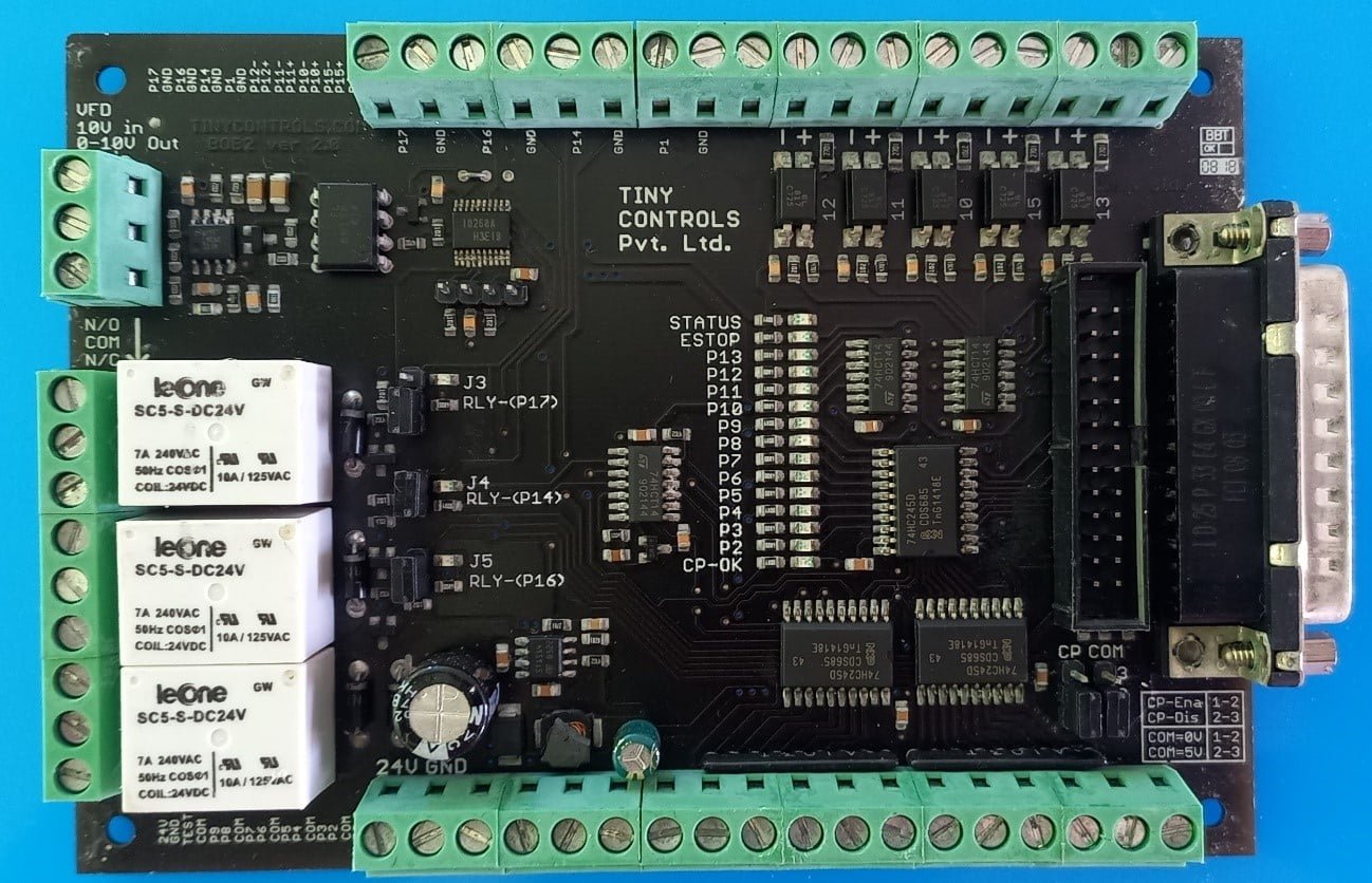
The Breakout Board (BOB) translates signals between the CNC machine and PC while isolating the PC motherboard from electrical surges. The BOB gives step and direction outputs to steppers for up to 4 separate axes. The outputs for X-Axis (or Y, depending on the CNC design) are buffered twice and received from two different connectors to make the board useful for gantry-style machines as well. All the outputs are buffered and received through screw terminals from the board.

These outputs can be received in Pull Up or Pull Down states and the motor Common output signal can be set as low or high by changing the jumper configuration.

Three relays are provided on the board and an isolated PWM to 0-10V analogue output circuit is provided for controlling the spindle speed. An onboard 5V regulator is given with a 5V output terminal.

An onboard charge pump is provided for the safety of the card. It is jumper configurable and it can be operated from frequencies as low as 200Hz to more than 15 kHz. The charge pump can be set disabled and this buffered output can be used as general-purpose output by changing the position of the respective jumper.

Input terminals compatible with 5-24V are given on the board. These are filtered for noise immunity ensuring that there is no error. LED indicators for inputs and outputs make the signal debugging task easy. All the outputs can also be used as general-purpose outputs.

A DB-25 connector and 26-pin box header are required to connect to the PC (Parallel Port Cable)

Specifications

Communication terminals: Parallel port terminal for connection with PC & 26 pins box header

Axes: 4 axes and X / Y Slave

Axes drive control type: Step/ Dir

Digital outputs: 14

Digital inputs: 5

Analogue output (0-10V) isolated: 1

Analogue output 5V: 1

Relay: 3

Supply Voltage: 24V DC (0.5 A)

Out of the Box Configuration

The Akriti 4 Axis CNC in the Mighty XL, Majestic and Mega series are Gantry Style machines with the Y-axis driven by twin stepper/servo motors. The machine comes preconfigured with the following pin & wiring configuration.

Axes outputs

The Parallel Port Break out Board has dedicated Step, Dir and COM outputs for four independent axes named X, Y, Z and A-axis. The Y-axis outputs are double-buffered and received through two individual terminals allowing easy connection to two motors on the same axis. The Y-axis Direction Signal is inverted for the current machine configuration

In total, there are five 3 pins terminals connectors with signal Com, Step and Direction.

Pin

Out of Box Configuration

Invert

COM

A COM


P9

A Direction


P8

A Step


COM

Z COM


P7

Z Direction


P6

Z Step


COM

X COM


P5

X Direction


P4

X Step


COM

Y COM


P3

Y Direction

Yes

P2

Y Step


COM

Y COM


P3

Y Direction

Yes

P2

Y Step


Limit Switches and E Stop

The board has five Opto-isolated inputs connected to signals P10, P11, P12, P13 and P15. All inputs are filtered for noise immunity and are active low. Active low means that when the input of the optoisolator is driven, the signal becomes low.

These inputs are used for the following functions

Pin

Out of Box Configuration

Invert

P10

X-Axis Home


P11

Y-Axis Home


P12

Z-Axis Home


P13

Unused


P15

E Stop


Spindle Control

By default, spindle control is disabled out of the box, however, the customer can choose to enable the same using the following Pins on the Parallel Port Board that are interfaced with the respective pins on the VFD.


A 0-10V analogue output signal goes directly to VFD to control the spindle. This circuit is completely isolated from the rest of the control board. If 10V input is fed from VFD to terminal 10V Analog IN; an analogue output in the range of 0-10V can be drawn from terminal 0-10V Analog OUT. If 5V input is fed from VFD to 10V Analog IN, an analogue output in the range of 0-5V can be drawn from terminal 0-10V Analog OUT terminal. The output voltage can be set through the POT connected.

Table of Contents