Overview of CAD/CAM process
CAD/CAM in the CNC world
CAD/CAM is a composite entity comprising two elements – Computer-Aided Design (CAD) and Computer-Aided Manufacturing (CAM). Together, CAD/CAM help in the design and manufacturing of prototypes and finished products across various industries, such as aerospace, automobile, medicine, military, and more! CAD & CAM together have ushered in the era of automation and autonomy in manufacturing, which is now the trend for maintaining resilience in production.
In this lesson, we will take a look at the components of CAD/CAM and how they contribute to CNC machining.
CAD (Computer Aided Design) is a software tool used to create 2D or 3D computer models based on common geometric patterns. These technical drawings and models allow designers, engineers, drafters, and architects to test an object through simulations before realizing it and subjecting it to real-world conditions. Upon running such tests, professionals can make informed decisions on changing the specifications or any other design parameters to improve efficiency or durability.
CAM (Computer Aided Manufacturing) utilizes the geometric design data present in CAD files as input in the creation of program logic (referred to as cutting tool paths) that will instruct and automate the CNC mill during production. Once the CAM user completes their toolpath logic, they will post-process it into a set of instructions (i.e., a program) for the CNC mill to follow. These instructions strictly adhere to international standards such as ISO-6983. This instruction program is referred to as G-Code named after the subset of operation codes (G00, G01, G03, etc.) used within the standard.
The G-Code program is then transferred from the CAM application to the mill. This is performed either directly using an interface cable, referred to as DNC (Direct Numerical Control) or manually using a USB thumb drive referred to as CNC (Computer Numerical Control). The process of CAM to CNC greatly speeds the production process without trade-offs on design, material strength, and/or accuracy.
Below image is of a typical CAD/CAM IDE.

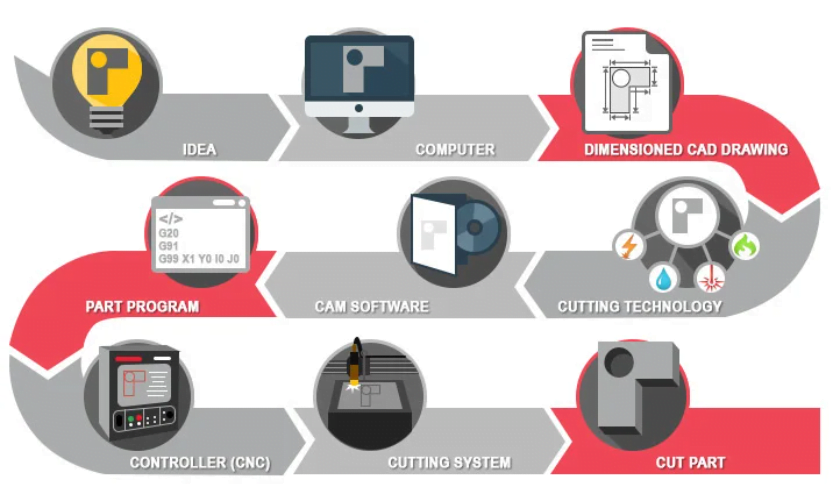
The below flow chart is a good illustrations to see how things progress from an idea to an actual part.
Advantages of using CAD/CAM with CNC Machines –
- Higher Efficiency
- Faster Project Turnaround
- More Control Over Your Project
- Less CNC Training Required
- Increased CNC Machine Productivity
- Eliminate Mistakes and Waste
Disadvantages of using CAD/CAM with CNC Machines –
- Cost and processing power limitations.
- Software Complexity
- Technological failures/glitches
In any case, the benefits of using CNC CAD CAM in machining vastly outweigh the disadvantages and risks. It’s important to consider both when making a big software or hardware purchase for your business.